- Kataloge
- EHRET GmbH
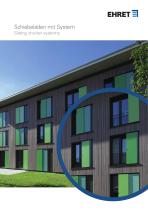
- Schiebeläden mit System
Schiebeläden mit System
1 /68Seiten

Schiebeläden mit System
1 /68Seiten
Katalogauszüge
Schiebeläden mit System Sliding shutter systems
Katalog auf Seite 1 öffnen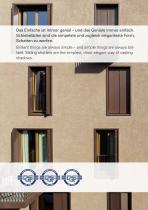
Das Einfache ist immer genial – und das Geniale immer einfach. Schiebeläden sind die simpelste und zugleich eleganteste Form, Schatten zu werfen. Brilliant things are always simple – and simple things are always brilliant. Sliding shutters are the simplest, most elegant way of casting shadows.
Katalog auf Seite 2 öffnen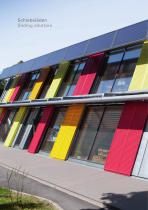
Schiebeläden Sliding shutters
Katalog auf Seite 4 öffnen
Modelle Models (Lamellen geschlossen | Slats closed) SUN-MAX48V (Lamellen geöffnet | Slats opened) Auszug aus unserer Produktpalette von über 80 verschiedenen Modellen. | E xcerpt from our product range of over 80 different models.
Katalog auf Seite 5 öffnen
Modelle Models Auszug aus unserer Produktpalette von über 80 verschiedenen Modellen. | E xcerpt from our product range of over 80 different models.
Katalog auf Seite 7 öffnen
Rahmenprofile Frame profiles
Katalog auf Seite 8 öffnen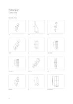
Füllungen Centres Lamellen | Slats
Katalog auf Seite 10 öffnen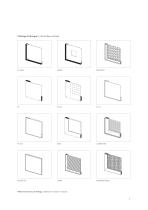
Flächige Füllungen | Full-surface centres Weitere Varianten auf Anfrage. | Additional models on request.
Katalog auf Seite 11 öffnen
Min./max. Maße Min./max. dimensions Untere Führung Typ Lower guide type PLANO VARIO CADROTEX CADROTEX Anst. von Querfries Instead of horizontal cross-panel Anst. von Längsfries Instead of vertical cross-panel Längsfries ab Breite Vertical cross-panel from width Modellname Model name Rahmen Frame Querfries ab Höhe Horizontal cross-panel from height Schiebeläden | Sliding shutters Alle Maße in mm | All dimensions in mm Flügel mit grösseren oder kleineren Maßen sind bei einigen Modellen nach technischer Klärung möglich. Smaller or larger sashes can be used with some models providing technical issues...
Katalog auf Seite 12 öffnen
Quer- / Längsfries Horizontal cross-panel / vertical cross-panel Untere Führung Typ Lower guide type Anst. von Querfries Instead of horizontal cross-panel Querfries ab Höhe Horizontal cross-panel from height Anst. von Längsfries Instead of vertical cross-panel Längsfries ab Breite Vertical cross-panel from width Modellname Model name in. Breite 650 mm ab Höhe 2000 mm | min. width 650 mm from height 2000 mm m min. Breite 850 mm ab Höhe 3000 mm | min. width 850 mm from height 3000 mm zusätzlich mit Schraublamelle ab Breite 1200 mm | additionally with screw slat from width 1200 mm z usätzlich mit...
Katalog auf Seite 13 öffnen
Statische Elemente Static elements Querfries Q 60 Horizontal cross-panel Q 60 Rechteckrohre Rectangular tubes Längsfries Vertical cross-panel Stützprofil Support profile Schraubkanallamelle Slat screw channel MAX37 | MAX15 | R75 | R48 in Verbindung mit SUN-L54 | PARIS | SL-Lamelle MAX37 | MAX15 | R75 | R48 in combination with SUN-L54 | PARIS | SL-Lamelle
Katalog auf Seite 15 öffnen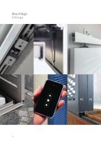
Beschläge Fittings
Katalog auf Seite 16 öffnen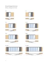
Anschlagschemen Stop diagrammes 1/R
Katalog auf Seite 18 öffnen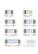
3/LLL-RRR Die Anschlagschemen werden von innen betrachtet bezeichnet. Die Bezeichnung 2/LL-R steht für 2 Laufschienen, 2 Flügel links (LL) und 1 Flügel rechts (R). The stop diagrammes are sketched as if viewed from the inside. The term 2/LL-R stands for 2 rails, 2 sashes left (LL) and 1 sash right (R).
Katalog auf Seite 19 öffnen
Aufhängungen oben Suspensions, top
Katalog auf Seite 20 öffnen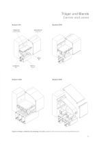
Träger und Blende Carrier and cover System A75 Trägerprofil C arrier profile System A105 Abdeckblende C over trim Laufschiene Rail Rahmen Frame Systeme mit Träger und Blende sind werkseitig vormontiert. | Systems with carrier and cover are pre-assembled ex factory.
Katalog auf Seite 21 öffnen
System A75 System A75 Durchgehendes Trägerprofil und Blende. Die Blende wird mit Blendenbügeln unsichtbar befestigt. Continuous carrier profile and cover trim. The cover is invisibly attached with cover brackets. System A75 | ECO 60 | BT 32 | Typ A System A75 | ECO 60 | BT 32 | Type A System 75 | ECO 60 | BT 48 | Typ A System 75 | ECO 60 | BT 48 | Type A 75 benötigte Einbauhöhe | Required installation height Wandabstand | Wall clearance x gerader Wandwinkel = 27,5 mm, gekröpfter Wandwinkel = 35 mm x straight wall bracket = 27.5 mm, offset wall bracket = 35 mm y gerader Wandwinkel = 30 mm, gekröpfter...
Katalog auf Seite 22 öffnen
System A105 System A105 Durchgehendes Trägerprofil und Blende. Die Blende wird mit Blendenbügeln unsichtbar befestigt. Continuous carrier profile and cover trim. The cover is invisibly attached with cover brackets. System A105 | ECO 60 | BT 32 | Typ A System A105 | ECO 60 | BT 32 | Type A System A105 | ECO 60 | BT 70 | Typ A System A105 | ECO 60 | BT 70 | Type A benötigte Einbauhöhe |Required installation height Wandabstand | Wall clearance 12 (b) 15 (b) Ladenführungsprofil Typ C ab 3000 mm Flügelhöhe verwenden | Shutter profile guide type C from 3000 mm sash height * 43 mm bei unterer Führung Typ...
Katalog auf Seite 23 öffnen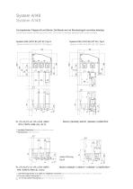
System A75 A148 System System A75 A148 System DurchgehendesTrägerprofil Trägerprofilund undBlende. Blende.Die DieBlende Blendewird wirdmit mitBlendenbügeln Blendenbügelnunsichtbar unsichtbarbefestigt. befestigt. Durchgehendes Continuous carrier carrier profile profile and and cover cover trim. trim. The Continuous The cover cover is is invisibly invisibly attached attached with with cover coverbrackets. brackets. A148| ECO | EC O6060| BT | BT3232| Typ | TypAA System A75 A148| |ECO ECO60 60| |BT BT32 32| |Type TypeAA System A75 System | EC O | BT | Typ SystemA148 75 | ECO 6060 | BT 4848 | Typ AA System...
Katalog auf Seite 24 öffnen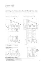
System A195 System A195 Aufhängesystem mit Wand-Basisprofil und einzelnen Trägern zum Einhängen. Die geteilte Blende besteht aus zwei Strangpressprofilen mit Steckverbindung. Die Blende wird mit Blendenbügeln unsichtbar befestigt. Suspension system with basic wall profile and individual carriers for attachment. The divided cover consists of two extruded profiles with plug connections. The cover is invisibly attached with cover brackets. System A195 | ECO 60 | BT 48 | Typ A System A195 | ECO 60 | BT 48 | Type A System A195 | ECO 60 | BT 70 | Typ A System A195 | ECO 60 | BT 70 | Type A benötigte Einbauhöhe...
Katalog auf Seite 25 öffnen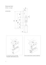
Basiswinkel Basic angle
Katalog auf Seite 26 öffnen
Deckenmontage Ceiling installation 2-Läufig mit R75-Rahmen | 2-rail with R75 frame 2-Läufig mit MAX-Rahmen | 2-rail with MAX frame 3-Läufig mit MAX-Rahmen | 3-rail with MAX frame Deckenmontagen erfolgen über Schienenkombinationen. Es stehen zwei Decken-Laufschienen mit Schienenbreiten von 33 und 55 mm zur Verfügung (Höhe: je 56 mm). Shutters can be ceiling-mounted using rail combinations. Two ceiling rails with rail widths of 33 and 5 5 mm are available (height: 56m
Katalog auf Seite 28 öffnenArchivierte Kataloge
 Schiebeläden
24 Seiten
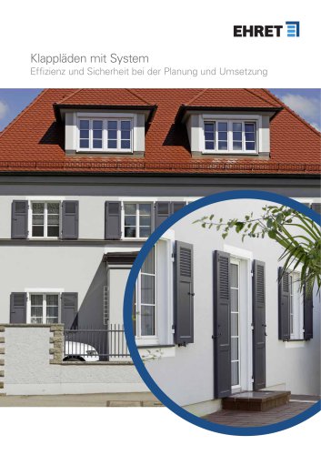 Klappläden mit System
72 Seiten
 Klappläden
24 Seiten
- Fensterladen
- Metall-Fensterladen
- Aluminium-Fensterladen
- Fensterladen für Privatgebrauch
- Lamellen-Fensterladen
- Fensterladen für Gewerbegebrauch
- Elektrischer Fensterladen
- Sicherheits-Fensterladen
- Einflügeliger Fensterladen
- Schiebe-Fensterladen
- Holzoptik-Fensterladen
- Holzfensterladen
- Fensterladen / Farbe anpassbar
- Fensterladen nach Maß
- Grauer Fensterladen
- Matter Fensterladen
- Wärmeisolierter Fensterladen
- Faltbarer Fensterladen
- Fensterladen für Fassade
- Motorisierter Fensterladen